


Design, construction and commissioning are three important links to ensure the normal operation of the purification air conditioning system. Many books and documents have been specially introduced for the design and construction of the purification air conditioning system. However, there are relatively few materials for the commissioning of the purification air conditioning system and the practical problems encountered in the commissioning. In the process of debugging several purification air conditioners, the author found the following problems that need attention and discussion.
Operating room purification workshop purification laboratory purification
The problem of changing the return air outlet of clean room into the supply air outlet
According to the process requirements, there should be a certain static pressure difference between adjacent clean rooms. On the one hand, when the doors and windows are closed, the air in the clean room with low cleanliness should be prevented from penetrating into the clean room with high cleanliness from the gap; on the other hand, when the door is opened, enough air flow should be ensured to flow in the positive direction, so as to minimize the reverse caused by the opening action and the instantaneous entry of people Flow to air to reduce pollution. However, in practice, due to design or other reasons, in order to ensure a large static pressure difference in the "relatively important" room, there will be a phenomenon that the "less important" clean room air return outlet becomes the air supply outlet, which is quite common in the process of purification commissioning. The analysis is as follows:
1.1 it is difficult to determine the design return air volume to maintain room pressure difference
In the design of purification air conditioning, the designers tend to focus on the design of the air supply volume of the clean room. For the design of the return air volume, the budget is usually adopted, that is, the return air volume is less than the air supply volume to ensure a certain pressure difference. However, the pressure difference between adjacent rooms is greatly affected by the site conditions, which is mainly the size of the room door gap. If the sealing performance of the door is good, a small difference between the air supply and return can ensure the opposite pressure difference required by the room. If the sealing performance of the door is poor, a large difference between the air supply and return is required to ensure the positive pressure difference of the clean room during the design. Therefore, in the field debugging, even under the condition of ensuring the designed supply air volume and return air volume of the clean room, the pressure difference of the adjacent rooms will also be inverted. Based on this situation, during the actual commissioning, the air volume distribution is carried out for the clean room according to the designed air volume, and the return air volume is adjusted appropriately according to the requirements of ensuring the pressure difference on site. The author has tested the air supply and return air volume of the clean room which has been adjusted. It is found that the deviation between the return air volume and the designed return air volume can be achieved sometimes when the air supply volume is within 10%. Of course, this does not mean that there is no need to calculate the return air volume in the design, but that the design is carried out according to the ideal state, and for the actual clean room, the influencing factors sometimes cannot even be controlled and predicted.
1.2 unreasonable design of return air pipeline
Although the return air volume of the clean room deviates greatly from the design value, if the return air pipeline is well designed, the commissioning of the pressure difference in the clean room can be better carried out to avoid the occurrence of problems. On the contrary, if the design of return air pipeline is unreasonable, the resistance deviation of parallel branch pipe is too large, and the residual pressure of the selected air conditioning unit is obviously insufficient, in order to ensure the relative positive pressure difference of all rooms on a return air pipe branch to the outdoor, so as to reduce the total return air valve on this branch pipe, it will often cause the reverse flow of the return air outlet of other rooms on the same branch pipe, that is, the return air outlet will become the supply air Mouth. We qualitatively analyze and illustrate this problem with figures 1 and 2.
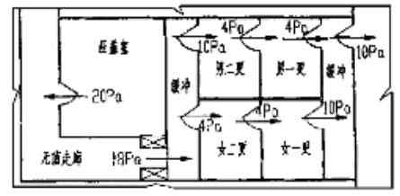
Figure 1 Schematic diagram of pressure distribution in clean room
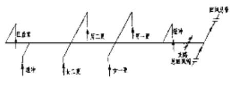
Figure 2 Schematic diagram of return air duct in clean room
Figure 1 is the layout plan of the rooms, and the actual pressure distribution diagram of these rooms is given for the purpose of analysis. Figure 2 is the schematic diagram of the air return system of the corresponding rooms. It can be seen from the figure that the pressure difference between the gland chamber and the outdoor is 66pa, while the pressure difference between the buffer chamber and the outdoor is 28pa. If the negative pressure formed by the return air branch pipe on the whole return air pipeline is small enough to overcome the positive pressure formed by the gland chamber and the buffer chamber, the return air of the gland chamber will be pressed into the buffer chamber through the return air pipe. For other quasi clean rooms, the same is true, especially in order to ensure the positive pressure difference with the outer corridor, when the return air regulating valve of the branch pipe is turned down, the phenomenon that the return air outlet changes into the supply air outlet often occurs. Of course, further theoretical analysis can also be based on the differential pressure characteristics of the pipeline. Generally, four major lines of the pipeline (total pressure line, potential pressure line, potential pressure line and zero pressure line) are drawn for detailed discussion, which will not be discussed here.
Therefore, the author suggests that the return pipe of the clean room with larger absolute pressure and the quasi clean area with smaller requirement should not be set on the same branch pipe as far as possible under the condition of site permission, so as to effectively avoid the problem that the return pipe becomes the air supply port. Of course, the appearance of this phenomenon has a great relationship with the residual pressure of the selected air conditioning unit, which should be paid attention to in the design.
2. Problems in disinfection and ventilation of clean room
The disinfection and exhaust of clean room are generally divided into two categories: one is regular exhaust of clean room, the production line of clean room needs to be fully sterilized after a certain period of operation, and the sterilized gas is discharged to the outdoor through the disinfection exhaust fan; the other is irregular exhaust during the operation of some special clean rooms, when the indoor pollutant concentration of clean production workshop reaches a certain degree, it is automatic (or manual) Exhaust. If the upper limit is not reached, the exhaust fan will stop running. The following problems often occur in the process of debugging.
2.1 the exhaust outlet changes into the air supply outlet
Exhaust air is set separately to exhaust some rooms. Due to the design of the pipeline, under the effect of different static pressure difference in the room, part of the exhaust outlets are backfilled and become the air supply outlets. The reason is the same as that the return air outlets become the air supply outlets. It is suggested that in addition to the reasonable selection of exhaust fan, the exhaust system should be set separately for the clean room with large pressure difference. If it is not allowed on site, it is also suggested to ensure that the exhaust outlet of the clean room with large pressure difference should not be arranged on the same branch pipe. It is worth mentioning that the centrifugal fan with higher resource pressure is used in the exhaust system of some purification rooms, which has better effect, and other systems can also be used for reference.
2.2 setting of regular disinfection and exhaust of the system
If the whole system needs to be sterilized regularly after the actual operation of the clean room for a period of time, it is reasonable to suggest to set up the system regular exhaust system on the air conditioning unit, as shown in Figure 3.
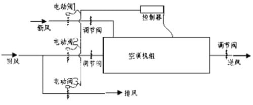
Fig. 3 Schematic diagram of regular disinfection and exhaust in clean room
In the figure, the electric airtight valve can reasonably use the return air pipe of the system to exhaust the air. The exhaust pipe, fresh air pipe and return air pipe are respectively equipped with electric control valves. When the system operates normally without exhaust, the fresh air electric valve 1 and return air electric valve 2 are opened, and the exhaust electric valve 3 is closed; when the system conducts regular exhaust, the fresh air electric valve 1 and exhaust electric valve 3 are opened, and the return air electric valve 2 is closed; when the whole system stops running, all electric control valves are closed.
It is worth mentioning that although the above exhaust system solves the problem of regular exhaust, another problem may occur in the field commissioning of such a system: when the system is in normal operation, if the electric valve 3 is not tightly closed and the residual pressure of the air conditioning unit is large, the fresh air will be sucked into the air conditioning unit through the exhaust pipe. In addition to the reasonable pipeline layout in design, the most important way to prevent this problem is to ensure the selection of valves with high quality from manufacturers.
2.3 precautions for irregular disinfection and ventilation in clean room
During the operation of the room, most of the irregular exhaust systems are not designed
In one step, in addition to the one-way valve to prevent backflow, it is recommended to set the electric control valve to automatically open and close with the opening and stopping of the exhaust fan. In this way, on the one hand, it can prevent a large amount of treated air from gushing out through the exhaust duct under the effect of indoor pressure difference, resulting in energy waste; on the other hand, it can reduce the noise caused by a large amount of outdoor air flowing out through the exhaust outlet during non operation time. For example, the author debugged on the second floor of a purification workshop, where the plane pressure distribution of the aseptic room and the section layout of the roof exhaust fan are shown in Figure 4, figure 5:
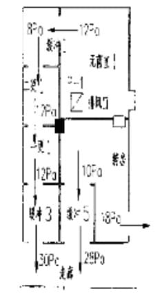
Fig. 4 plane pressure distribution of sterile room
Fig. 3 Schematic diagram of regular disinfection and exhaust in clean room
In the figure, the electric airtight valve can reasonably use the return air pipe of the system to exhaust the air. The exhaust pipe, fresh air pipe and return air pipe are respectively equipped with electric control valves. When the system operates normally without exhaust, the fresh air electric valve 1 and return air electric valve 2 are opened, and the exhaust electric valve 3 is closed; when the system conducts regular exhaust, the fresh air electric valve 1 and exhaust electric valve 3 are opened, and the return air electric valve 2 is closed; when the whole system stops running, all electric control valves are closed.
It is worth mentioning that although the above exhaust system solves the problem of regular exhaust, another problem may occur in the field commissioning of such a system: when the system is in normal operation, if the electric valve 3 is not tightly closed and the residual pressure of the air conditioning unit is large, the fresh air will be sucked into the air conditioning unit through the exhaust pipe. In addition to the reasonable pipeline layout in design, the most important way to prevent this problem is to ensure the selection of valves with high quality from manufacturers.
2.3 precautions for irregular disinfection and ventilation in clean room
During the operation of the room, most of the irregular exhaust systems are not designed
In one step, in addition to the one-way valve to prevent backflow, it is recommended to set the electric control valve to automatically open and close with the opening and stopping of the exhaust fan. In this way, on the one hand, it can prevent a large amount of treated air from gushing out through the exhaust duct under the effect of indoor pressure difference, resulting in energy waste; on the other hand, it can reduce the noise caused by a large amount of outdoor air flowing out through the exhaust outlet during non operation time. For example, the author debugged on the second floor of a purification workshop, where the plane pressure distribution of the aseptic room and the section layout of the roof exhaust fan are shown in Figure 4, figure 5:
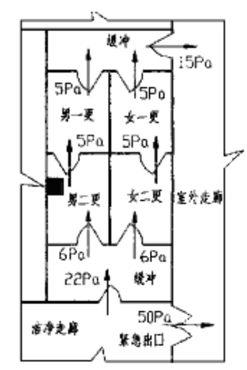
Figure 6 schematic diagram of quasi clean area
3.2 there is no buffer room at the emergency exit leading to the outdoor
For the setting of buffer room at emergency exit. Different designers have different opinions, but the author suggests adding buffer room from the perspective of debugging. Figure 6 is a practical example of a project. From the point of view of pressure difference, the pressure difference between the clean walk and the outdoor corridor is as high as 50pA. Under the effect of such high pressure difference, the door crack at the emergency exit is very loud. In addition, if the door is opened in case, the pressure of the whole clean walk will be released, and some rooms in the clean room will show the phenomenon of pressure backflow. If a buffer room is set and air is supplied to it, this situation will be completely avoided. It is worth noting that the opening direction of the buffer room door should not be towards the side with high pressure (i.e. clean walk profile), but should be the same as the opening direction of the emergency exit door.
4. Problems of regulating valve
4.1 ordinary air volume regulating valve
Due to the different manufacturers, the quality of the valve is very different. Many debugging problems on site are caused by the valve opening and closing not working properly. For example, when debugging an electronic production workshop, an air conditioning unit opens the air supply valve no matter what, its air volume is always the same. After inspection, it is found that the valve blades are misplaced, 90 degrees of each other. Whether fully open or fully closed, half of them are always open, Half closed. Another problem about the valve is that there is no opening and closing position mark, so it is impossible to judge whether the valve is open or closed. Only through the test can we know, which brings difficulties to Party A's future management. Therefore, it is suggested that Party A should fully consider the convenience of future management and maintenance when selecting valve manufacturers.
4.2 fire control valve
At present, most of the purification air-conditioning units are equipped with fire dampers at the outlet. In theory, on the one hand, they play a role in fire prevention, on the other hand, they can also regulate the air supply or return volume of the unit. However, in the actual debugging, it is found that the regulating function of most of the current fire dampers is very weak, because it is difficult to ensure that the adjusted air volume can meet the design requirements by using the gear adjustment (generally 5 or 6).
For example, when the air conditioning unit is commissioned in a purification workshop, the air volume of the fire control valve of the air supply main pipe of the unit is too small to open the third gear, but the air volume is too large to open the fourth gear. Similarly, the fire damper on the main return air pipe also has the problem of small regulation. In order to ensure the relative pressure difference between two different purification systems, in the case of a small adjustment range of fresh air volume, it is necessary to further adjust the air volume of the air conditioning unit of one system, and the relative pressure difference caused by the opening and closing of the return air fire damper is too large to meet the design, specification and actual site requirements. Of course, this situation also has a great relationship with the regulating flow characteristics of the valve, but due to the limit of the gear, the regulating flow characteristics of the valve itself become worse.
At the same time, it was found that the opening and closing of the fire damper were not effective during the commissioning. Some fire dampers could only be fully opened or fully closed, and could not be fastened when they were in other gears, so they lost their regulating function completely. Therefore, the author thinks that it is better to set the fire damper and the regulating valve separately when it is allowed on site. The regulating valve is suggested to use the continuously adjustable regulating valve instead of the discontinuous regulating valve with less gears.
5 problems of air conditioning unit
It is found that some air conditioning units blindly pursue structural compactness, blindly shorten the distance between the fan outlet section and the filter section, and do not take other remedial measures (such as installing a flow equalizing plate at the fan outlet), so that the treated air is too late to spread, so that the air filtration speed of the whole section of the medium efficiency filter at the fan outlet is extremely uneven, which not only affects the filtration effect of the filter, Moreover, the service life of the filter is greatly shortened.
At the same time, the poor overall sealing performance of the unit is a very common phenomenon at present. When some power cables of air conditioning units (such as motor power line and fan power line) pass through the chassis, the connection between them and the chassis board is not sealed tightly, or even without any treatment; at the same time, it is found that the air leakage around the access door of the air conditioning unit is also serious, and the noise of the access door of the unit often occurs. Therefore, it is suggested that the manufacturer should strictly close the quality, and the access door should not only meet the requirements of operation, but also ensure the tightness of the air leakage rate measurement method of the inspection unit specified in the national standard GB / t1494-93 [1] when the positive pressure is 700pa. When the air conditioning unit is tested in a factory, the air leakage rate of the filter unit cannot be tested because of the serious air leakage (the pressure in the unit cannot reach 700pa).
In the field, the air volume of the surface cooler of the air conditioning unit is larger than the air volume of the nameplate of the fan in the unit, no coarse effect filter screen is installed at the fresh air intake, no differential pressure gauge is installed at the filter section of the unit, and the location of the access door is unreasonable. As long as engineering and technical personnel and manufacturers pay attention to the problems and make efforts to improve, we believe that the purification air conditioning will have a great change.
Shandong ed purification Engineering Co., Ltd. focuses on laboratory system engineering, medical purification engineering, purification workshop, clean room system engineering. It has relevant business qualifications in the industry, from engineering consulting design, construction management, equipment and consumables supply, technical services, to laboratory certification, maintenance management, etc., to provide a comprehensive and complete solution for the medical purification engineering, laboratory system engineering, purification workshop system engineering industry. For more knowledge of medical purification industry, please pay attention to WeChat public address: Aide-188 (Ed purify oxygen supply).
- About Us
-
- Company Profile
-
- Honor
-
- Growing experience
-
- The enterprise culture
-
- Equity structure
-
- Join Aide
-
- The wind calculation show
-
- Service support
-
- Sales network
-
- Organizational structure
- News
-
- Company news
-
- Industry Information
-
- conceptual design
-
- Equipment maintenance
-
- technical service
-
- Data Download
-
- Cleaning principle
-
- Common problem
-
- Purification classification
-
- construction technology
-
- Purification drawings
-
- Supply information
- Products
-
- Purification engineering installation
-
- Purification equipment
-
- hepa box
-
- Supporting products of ED
-
- Laboratory support
-
- Medical Writing Table
-
- Control panel
-
- Stainless steel instrument cabinet
-
- Operating Room Air Source Box
-
- Medical viewing lamp
-
- return air grille
-
- Operating room socket box
-
- Medical Hand Washing Pool
-
- Transfer window
-
- Air shower
-
- Air filter
-
- Laminar air supply smallpox
-
- Clean lamp
-
-
- Medical Purification Door
-
-
- Suspension bridge crane series
-
- Bed and Ward Care Series
-
- Clean room air conditioning system
-
- Surgery table series
-
- Shadowless Lamp Series
- Cases
-
- Workshop purification engineering
-
- Hospital decontamination
-
- Laboratory decontamination
-
- National cleaning customer case
-
- Mobile Operating Vehicle Purification Project
-
- Air purification project
- Human Resources
-
- Human Resources
-
- Recruitment information
- Contact Us
-
- Contact Us
-
- Message